Fsm3s
2023. 6. 28. 13:46ㆍFPGA/HDLBits
728x90
See also: State transition logic for this FSM
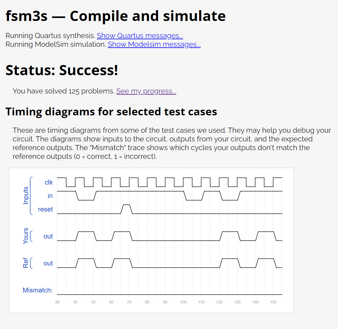
The following is the state transition table for a Moore state machine with one input, one output, and four states. Implement this state machine. Include a synchronous reset that resets the FSM to state A. (This is the same problem as Fsm3 but with a synchronous reset.)
StateNext stateOutputin=0in=1
| A | A | B | 0 |
| B | C | B | 0 |
| C | A | D | 0 |
| D | C | B | 1 |
module top_module(
    input clk,
    input in,
    input reset,
    output out); //

    parameter A = 0, B = 1, C = 2, D = 3;
    reg [1:0]State,Next_state;

    always @(*)begin
    // State transition logic
        case(State)
            A : Next_state = in ? B : A;
            B : Next_state = in ? B : C;
            C : Next_state = in ? D : A;
            D : Next_state = in ? B : C;
        endcase
    end

    always @(posedge clk) begin
    // State flip-flops with asynchronous reset
        if(reset)
            State <= A;
        else
            State <= Next_state;
    end
    // Output logic
    assign out = (State == D) ? 1'b1 : 1'b0;
endmodule
'FPGA > HDLBits' 카테고리의 다른 글
| Shift4 (0) | 2023.06.28 |
|---|---|
| Sim/circuit8 (0) | 2023.06.28 |
| Fsm3 (0) | 2023.06.28 |
| Fsm3onehot (0) | 2023.06.28 |
| Fsm3comb (0) | 2023.06.28 |